
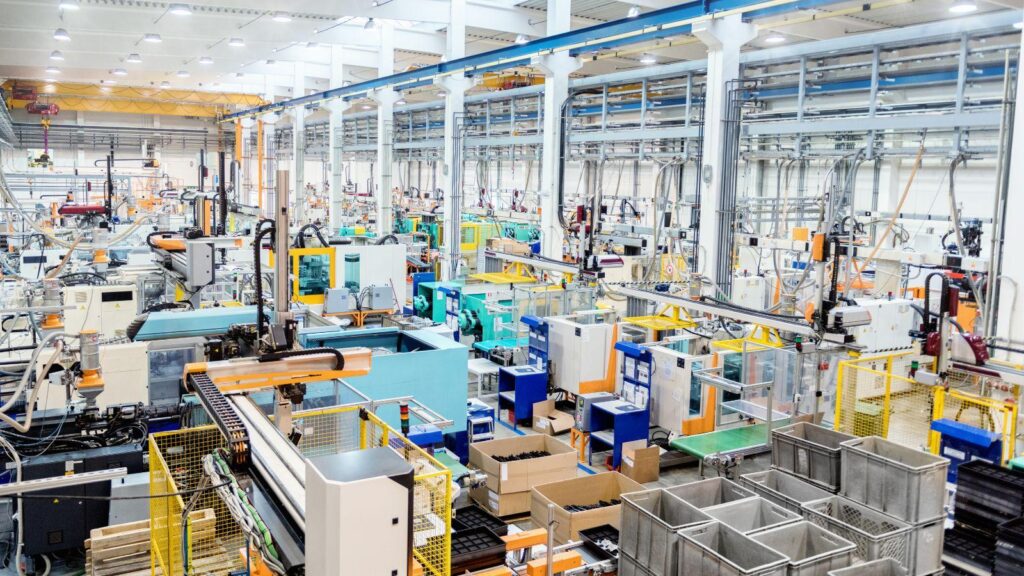
Developing a new physical product once involved long handoffs between designers, engineers, manufacturers, and quality teams. A concept might begin as a sketch, become a physical model, then move through several rounds of drawings, tooling, samples, and revisions before production could begin. Each transition created opportunities for delay, miscommunication, and expensive changes. Digital manufacturing connects these stages through shared digital information, allowing teams to move from an idea to a tested part with far less friction.
At its core, digital manufacturing uses software, connected machines, and production data to plan, make, inspect, and improve products. It does not eliminate engineering judgment or hands-on testing. Instead, it gives product teams faster ways to evaluate designs, identify manufacturing problems, and produce real components in suitable materials. From a startup testing a device enclosure to an established company refining industrial equipment, the result is a development process that is more iterative, informed, and responsive.
CAD Creates a Shared Starting Point for Product Decisions
Computer-aided design, usually called CAD, is the digital foundation of modern product development. Engineers use CAD software to create precise three-dimensional models that define a part’s shape, dimensions, holes, threads, internal features, and assembly relationships. These models can be shared with custom CNC machining services to support faster feasibility reviews and more accurate production planning. Unlike a hand-drawn concept, a CAD model can be measured, modified, analyzed, and transferred directly into manufacturing workflows.
A well-built model also helps different specialists work from the same source of information. Industrial designers can evaluate appearance and ergonomics, mechanical engineers can check fit and movement, and manufacturing teams can review whether a shape can be made efficiently. When a dimension changes, the updated model can be shared without relying on outdated drawings or informal explanations.
CAD supports virtual checks before material is cut. Assemblies can reveal whether a bracket interferes with a housing, whether fasteners have enough clearance, or whether a cable path is blocked by another component. Engineering teams may also run simulations to estimate how a part responds to force, heat, vibration, or fluid flow. These analyses are not substitutes for physical validation, but they help focus prototypes on the questions that still need real-world testing.
The model can then move into computer-aided manufacturing, or CAM, software. CAM translates geometry into machine instructions, often called toolpaths, that direct cutting tools across a workpiece. This connection between design and machining reduces manual interpretation and makes design revisions easier to carry into the next production run. It also creates a clearer record of which version of a part was made and how it was produced.
Automated DFM Identifies Problems Before Production Begins
Design for manufacturability, commonly abbreviated as DFM, means designing a product so it can be made reliably, economically, and at the required quality level. A part may look correct in CAD yet still be difficult to machine because a cutting tool cannot reach a feature, a cavity is too deep and narrow, or a thin wall may flex during cutting. Finding those issues after a prototype arrives costs time. Finding them while reviewing the digital model is much faster.
Automated DFM tools examine CAD files against manufacturing rules. Depending on the process, the software can flag inaccessible internal corners, extremely small holes, insufficient tool clearance, sharp internal edges, undercuts, or dimensions that require unusually tight tolerances. Some systems provide feedback soon after a model is uploaded, giving engineers an early view of likely cost, lead time, and feasibility concerns.
Tool access is a practical example. Standard milling cutters are round, so they leave rounded internal corners. If a designer specifies a perfectly square corner inside a pocket, a machinist may need a specialized process, a smaller tool, or an alternate design. Adding a suitable corner radius can make the feature easier and quicker to produce while preserving its function. Similarly, keeping pocket depths reasonable relative to their width can reduce vibration and improve accuracy.
Tolerance choices deserve the same attention. A tolerance states how much a finished dimension may vary from its nominal size. Tight tolerances are necessary for some bearing seats, sealing surfaces, and precision fits, but applying them to every feature increases machining and inspection demands. Digital reviews help teams reserve strict requirements for features that truly affect performance, while allowing less critical areas to use practical general tolerances.
Prototype CNC Machining Turns Digital Designs Into Functional Parts
Prototype CNC machining is especially valuable when a team needs parts that behave like intended production components. CNC, or computer numerical control, uses programmed instructions to control machine tools such as mills and lathes. A milling machine removes material with rotating cutters, while a lathe rotates the workpiece for features such as shafts, threads, and cylindrical profiles. Because CNC processes work from digital geometry, revised parts can be produced without creating dedicated molds or dies.
This method is useful for functional prototypes that must withstand loading, heat, wear, or assembly testing. For example, an aluminum mounting plate can be machined to verify bolt positions and stiffness in a robotics assembly. A stainless-steel fitting can be tested for thread engagement and corrosion resistance. A plastic enclosure can confirm whether connectors, buttons, and internal circuit boards align as intended.
Material selection shapes what a prototype can teach. Aluminum alloys are popular for their machinability, low weight, and useful strength. Stainless steels offer corrosion resistance and durability, although they can take longer to machine. Brass is often selected for fittings and electrical components, while engineering plastics such as acetal, nylon, polycarbonate, and PEEK can provide low friction, electrical insulation, transparency, or chemical resistance. Choosing a material close to the intended final material makes test results more meaningful.
Good prototype planning also considers the part’s purpose. An appearance model may prioritize surface finish and visible details. A fit-check part may focus on critical dimensions and assembly interfaces. A performance prototype should reflect the loads, materials, and operating conditions of the final application as closely as practical. Separating these goals prevents teams from spending money on features that do not answer the current development question.
Small-Batch Production Bridges Testing and Market Launch
After early prototypes prove that a design works, small-batch CNC machining allows teams to produce limited quantities without immediately committing to high-volume tooling. These runs may support pilot programs, customer trials, field testing, certification samples, repair parts, or an initial market release. They give companies a way to learn from real use while retaining the ability to adjust the design.
Small-batch production also exposes issues that a single prototype may not reveal. A part that machines well once might require a different fixture, tool sequence, or inspection method when dozens are produced. Repeating the process helps manufacturers evaluate consistency, cycle time, material yield, and the practical effects of tolerances. That feedback can improve both the part and the manufacturing plan before production volume rises.
The approach is useful when demand is uncertain, or product variants are numerous. Medical equipment, laboratory devices, industrial automation tools, and specialized vehicles may require several versions with modest quantities. Rather than carrying excess inventory or paying for separate tooling for every variation, teams can produce CNC machining parts in quantities that better match actual requirements.
Clear documentation matters at this stage. CAD revisions should be controlled, critical dimensions should be identified, and finishing requirements such as anodizing, bead blasting, powder coating, or passivation should be specified where needed. These details help ensure that the parts delivered for testing or release match the intended design.
Data and Connected Workflows Improve Each Development Cycle
Digital manufacturing does more than transfer a CAD file to a machine. It creates opportunities to capture information throughout the process. Machine programs, inspection reports, material certificates, production schedules, and revision histories can be connected to a specific part number. This traceability makes it easier to understand what changed between iterations and to investigate a problem if one appears later.
Inspection data is particularly useful for closing the loop between design and production. Coordinate measuring machines, calipers, gauges, and optical systems can compare finished dimensions with the CAD model or engineering drawing. If a recurring feature trends toward one side of its tolerance range, engineers and machinists can determine whether the issue comes from the setup, tool wear, material behavior, or the design itself.
Digital records also improve collaboration across locations. A product engineer may update a design, a manufacturing engineer may review the new geometry, and a supplier may prepare a production plan without waiting for physical documents to circulate. The speed of communication does not remove the need for approvals, but it helps teams make those approvals with current information.
As products become more complex, the strongest advantage is continuity. Design choices, manufacturing constraints, prototype results, and quality findings no longer need to sit in separate systems or individual inboxes. When information remains connected, each iteration can build on evidence from the last one rather than restarting the learning process.
A More Practical Path From Idea to Reliable Product
Digital manufacturing is changing product development by making iteration more direct and less dependent on disconnected handoffs. CAD provides a precise digital definition of the product, automated DFM helps prevent avoidable manufacturing difficulties, prototype CNC machining produces functional parts for real testing, and small-batch production validates repeatability before major commitments are made. Used together, these tools help teams make better design decisions earlier, refine products with tangible evidence, and bring well-tested products to market with greater confidence.